What
makes DataMetrics VME/PCI chassis more reliable, and keeps
them on top of the VME/PCI market? Well the answer is simple;
DataMetrics VME/PCI chassis are smarter than your average
chassis. What makes them smarter? DataMetrics has developed
a monitoring and control system that makes our VME/PCI chassis
the most sophisticated, self-protecting chassis on the market.
The Envirostat™ enables our VME/PCI chassis to monitor
and control their internal temperatures, power supply voltages,
system voltages and fan speed before damage can be done or
data lost. Now lets take a look at how the Envirostat works.
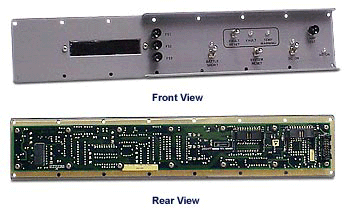
What is the Envirostat?
A data acquisition system and operator
interface is implemented on a circuit card that is also used
to mount the VME chassis control switches. The Envirostat
also includes a wide temperature range 24 Vdc power supply
that provides power to the cooling fans. This power supply
and the power supply for the Envirostat module are independent
of the main VME system power supply.
 The Envirostat automatically
monitors the chassis’ operating environment to protect
against damaging departures from proper operating conditions.
Warnings and faults are indicated, both with indicator lamps
and readable messages to alert personnel to the cause of the
fault.
Additional functions available include logging of fault occurrences,
provision for remote monitoring and control functions using
an RS-232 link, and convenient control software revision and
customization procedure.
 Temperature
Monitoring
This module provides to the system user
temperature data from the chassis power supply, air inlet
port, and fax exhaust port. The data is constantly checked
for fault conditions by a microprocessor and may be monitored
using the eight character alphanumeric display provided. Two
additional temperatures can be monitored for applications
that require that additional locations be monitored. These
might include high power CPU assemblies or other on-board
components.
The Envirostat computer makes use of temperature sensor data
to regulate chassis temperature by adjusting fan speed. This
is accomplished by controlling a digital to analog converter
that determines the Envirostat fan power supply voltage. Protection
against power-on is provided when the ambient temperature
is outside the programmed limits.
Up to three cooling fans are intelligently monitored and controlled.
The fan drives are fault monitored and should a fan stop functioning
the remaining fans can be commanded to operate at higher speeds.
VME Chassis Power Supply Voltage Monitoring
The Envirostat observes the primary system DC voltages. Voltage
excursions that constitute a fault condition are detected
and announced using both indicator lights and the alphanumeric
display. Because the Envirostat uses a high speed ten bit
analog to digital converter, rapid, accurate testing is performed
before declaring that a fault condition is indeed present.
As with all measured parameters, the VME chassis is deactivated
under fault conditions automatically unless overruled by the
operator.
Diagnostic Mode
If no faults are present the Envirostat can be set in a diagnostic
mode to report system measurements to the alphanumeric display.
Three switches are added to the standard control switches.
These are known as F1, F2 and F3. F1 is used to scroll through
the list of voltage measurements, F2 scrolls through the temperatures,
and F3 will display fan status. These switches also are used
to display code space checksum and select remote transmission
via RS-232. The standard data rate is 19.2kb.
Circuit/Software Implementation
An 8-bit 8051 microcomputer is programmed to supervise a 1-millisecond
system measurement cycle. VME system voltages are scaled with
precision resistors and presented to a multiplexer for selection
and buffering.
The buffered sample is presented to a 10-bit A/D converter
and within a few microseconds the 8 most significant bits
are stored in a memory location corresponding to the parameter.
A 4.096-volt precision reference is used for the A/D converter
and also buffered to excite the thermistor networks. Modern
high-speed 5-volt op amps are used to provide low impedance.
After all voltages have been measured a second multiplexer
is similarly accessed to measure the temperature of the fan
sensors. These slowly changing parameters are sampled using
sub-commutation and the data profile is accumulated over ten
cycles. Some data that is typically noisy is further filtered
through software averaging to provide reliable data.
After a high-speed frame is acquired it is examined for fault
or warning application. A fault limit and warning limit profile
is stored in table form in the microcomputer. If a limit is
exceeded that parameter is immediately rechecked twice. If
all measurements concur a fault is declared.
If normal operation continues the control panel is monitored
for operator requests such as VME RESET, POWER DOWN, etc.
These control panel switches are monitored through two 8-bit
ports and debounced by multiple sampling. The display is updated
through two output ports, one of which is an 8-character 5x7
dot matrix LED display. The other port drives the LED enunciators.
A third 8-bit port is used to configure the VME backplane
reset control and fan activation. Four spare input lines and
four spare output lines are provided (TTL level). A 2kb eeprom
is present to log diagnostic information should that option
be required.
A VME that can monitor and control its internal systems, adjusting
them before damage can be done, is a VME for today’s
high-tech military. |